Posted on 21st July 2020 at 10:27am
Harrop Engineering is in its 65th year of
Automotive Engineering design, development and manufacturing. For 15 of those years we have developed many
supercharger systems for both OEM and Aftermarket customers. We supplied the
world’s first Eaton TVS technology supercharger to Toyota Australia, a global
OEM, for the TRD Aurion program. Over 10 years ago we also worked on another
world first, this time with FPV to develop the Ford Miami OEM TVS Supercharged
Coyote engine.
Our focus has always been to develop complete, high quality
supercharger systems for a range of platforms including GM LS and LT, BMW S65,
R53 Mini, Ford 5.0 & 5.4, Toyota 3UR, 1UR and 2GR, Subaru FA20, Nissan
VK56, Hemi 5.7 and Holden 304– all designed and manufactured in Australia.
At Harrop we try not to get caught up in opinions and
beliefs, and prefer to deal with the facts. A hot topic for debate recently has been Supercharger
designs and the impact of Inlet Air Temperatures (IATs) delivered to the
engine.
Downwards vs Upwards Discharge
On the topic of supercharger layout, there are two common
types. One where the air exits the
supercharger downwards, and the other upwards.
There are advantages and disadvantages of each, and the design is
influenced by a number of factors including styling, available space,
serviceability, manufacturing cost, rotating group, intercooling requirements,
airbox and intake system, and very importantly – supercharger drive.
It is interesting to note that- all other things being equal,
neither design stands out as being significantly more efficient than the other.
Our design objective is to develop complete, high quality
supercharger systems while maximising the performance potential for our
customers. We test to better understand what happens to the air through the
induction side of the engine using our supercharger dyne cell, our vehicle dyne
cells and testing through data acquisition at the race track.
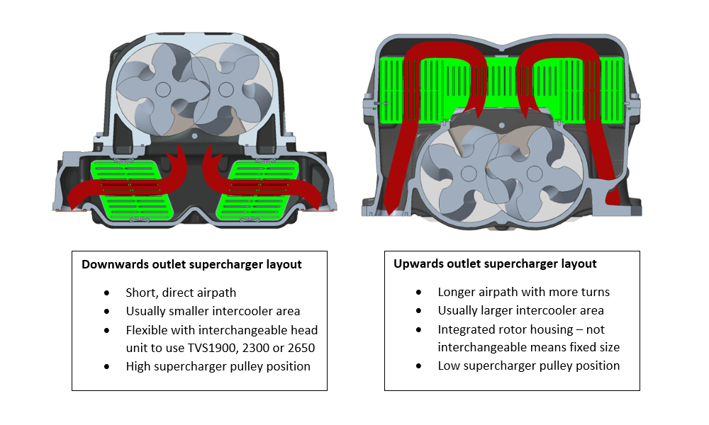
Below are cross-sections of two Harrop Supercharger manifolds, on the left a downwards outlet and on the right an upwards outlet. Green highlighted surfaces are the in-manifold intercoolers.
Red arrows indicate the general, schematic airflow path. In reality this is much more complex, turbulent, rarely in a straight line and varies tremendously with volume flowrate and pressure.
Air inlet is facing the reader into the ends of the 2x 4-lobe rotors in both cases.
Measuring IATs
Harrop Supercharger kits use a factory OEM sensor. We are confident that the engineers that
designed these sensors spent a lot of time designing for both accuracy and
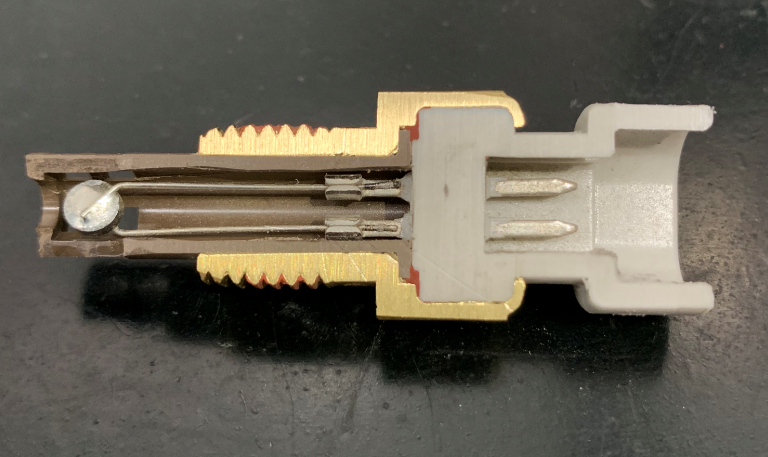
durability. The image below shows a sectioned IAT sensor to clearly show the construction
of the sensor. The brown and white
components are non-conductive plastic and the part that measures the
temperature is the circular thermistor hanging in free air on two thin wires at
the left, heat soak through the casting is minimal.
The sensor is designed to be accurate at the tip, even if
the brass body of the sensor is very hot.
Now let’s consider some key points regarding the position of
the IAT sensor:
·
Must be in
the post-intercooler airstream, close to an inlet port – need to know
accurately what temperature the cylinder head is receiving.
·
Not
directly facing an inlet valve – reversion can heat the thermistor
·
Avoid oil
contamination of the sensor
·
Avoid fuel
vapour which can cool the thermistor
All of these must be taken into consideration when choosing the position of the IAT sensor.
Our experience has shown that a high proportion of heat in
the inlet air is added by the supercharger itself, not from heat transferred
from the engine.
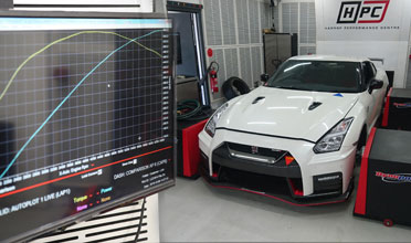
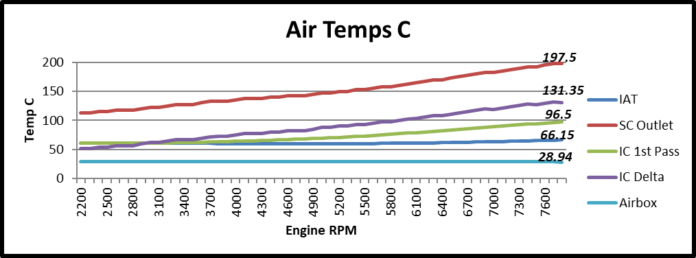
The following chart shows data from a TVS2650 Mustang on our
chassis dyno, where we added sensors and measured air temperatures throughout
the supercharger air path.
The light blue trace is the temperature of the air entering
the supercharger (constant at ~29°C). The
red trace is the temperature of the air exiting the supercharger (~198°C) before
any intercooling, and the dark blue trace is the IAT that the ECU uses, after
intercooling (~66°C).
The run start point has about 11 PSI of boost and the end
point just over 21 PSI. Whilst the
supercharger outlet temperature almost doubles the IAT is well under control
and increases by less than 30%. There is a lot of work done by the intercooler
system to achieve this type of result.
Intercooler System Testing
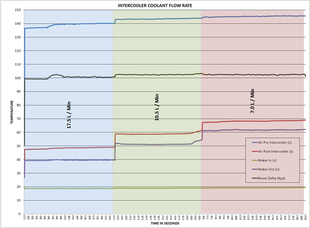
Below is a graph from our supercharger test cell measuring different
intercooler water flow rates and the effect of the air temps and the
intercooler water temperatures.
As you will note the lower the coolant flow rate the higher
the IAT. This data is from one of our
kits tested on our supercharger dyne cell (not on an engine).
Welcome to Harrop Engineering
Since 1955, Harrop has engineered and manufactured world-class systems and solutions for OEMs, Race Teams and the Aftermarket. #harrop